Gas Fuel Tank Plumbing 101
 Items you need
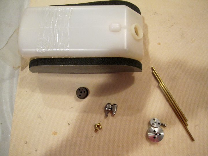
Here's the list of the items you will need:
- Fuel Tank - The Fuel Tank pictured here is out of my 1/3 Scale SIG Spacewalker. I'm retrofitting it, because it has been several years since I changed the fuel lines in it.
- Fuel Tank Cap - I prefer the Aluminum caps by PSP - These are available at Thunderboltrc.com at this link: Click Here
- Fuel Tank Stopper - Compatible with Gasoline. This is very important! I have found that the Dubro Gas Conversion Stopper is the best. These are available at Thunderboltrc.com at this link: Click Here
- Brass Tubing (This usually comes with the fuel tank, and you generally use 1/8" Outside Diameter brass tubing). You will need two or three pieces of brass tubing depending on the number of clunks you use. - See info below.
- Fuel Line Clunk(s) - You can use one or two clunks - See info below. I perfer the filtered clunks by PSP. These are available at Thunderboltrc.com at this link: Click Here
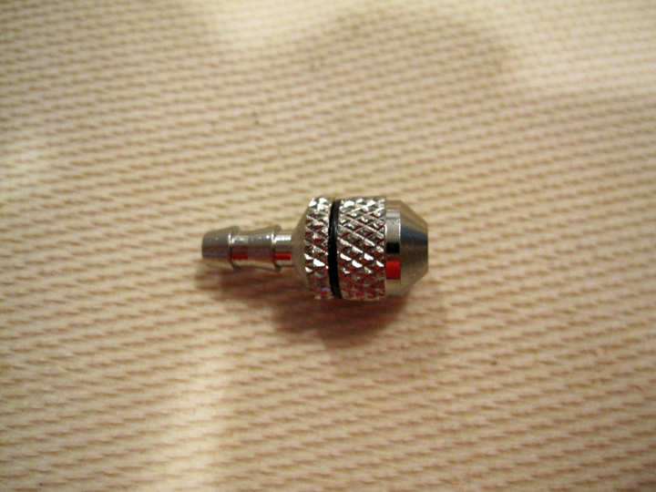
- Fuel line Barbs - These are available at Thunderboltrc.com at this link: Click Here
- Fuel line - for inside of the tank and to run to your engine, fuel dot, and vent line. See below for Fuel Line info.
- Wire Ties
- Solder and Solder Iron or Torch
Fuel Line Info
Every Gasoline Fuel Tank installation will require fuel line. You generally need gas fuel line for inside the fuel tank (clunk line) and for outside the fuel tank (Fuel line to engine, vent line, refill line). There are many different types of Fuel Line available for R/C aircraft. In this tutorial we are only focusing on Fuel Line that is compatible with gasoline.
When selecting Gas Fuel Line, you must consider the application and the "type" of gasoline that you will use. Often the gasoline you buy at the pump will include additives like Ethanol that will affect the Gas Fuel Line you use.
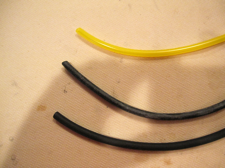
In the picture to the right, there are 3 types of Gasoline Fuel Line. From the top down, they are:
Preparing the Brass Tubing
The first step in plumbing a Gas Fuel Tank is to prepare the brass tubing for the Fuel Barbs. You will have to decide what kind of install you want to do. For a gasoline engine, you will need three gas "lines". One line from the tank to the engine, one vent line and one refill line. Some prefer using one clunk line and using a T-connector on the main clunk line to run a fill line. Some prefer to use two clunk lines (one as the main line to the engine, and one as a fill line). It is really up to you and your particular installation. If you decide to go with two clunk lines, you will need three lengths of brass tubing (one for each clunk, and one for the vent line). If you decide to go with one clunk line, you will need two lengths of brass tubing (one for clunk, and one for the vent line).
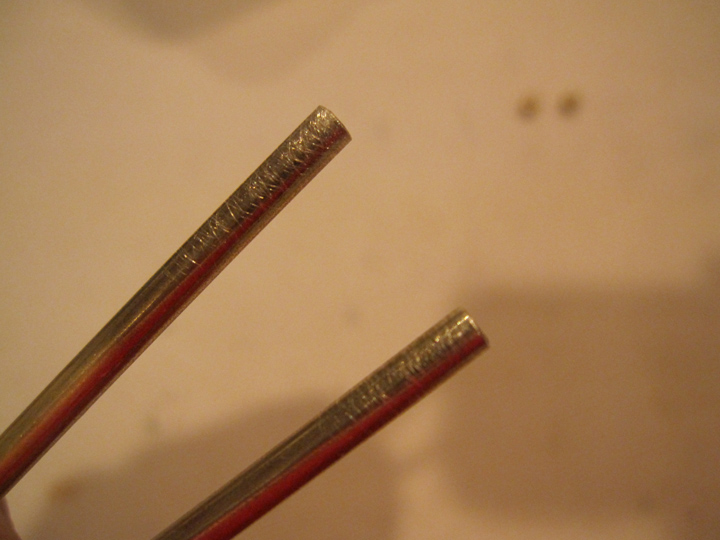
For the purposes of this tutorial, I will be doing a two clunk line install. Once you have decided, you need to prepare the ends of the brass tubing for each clunk line(s) by lightly sanding them. Once sanded, clean the Brass tubes with Alcohol. (The brass tubing for the vent line does not require sanding).
Solder Barbs
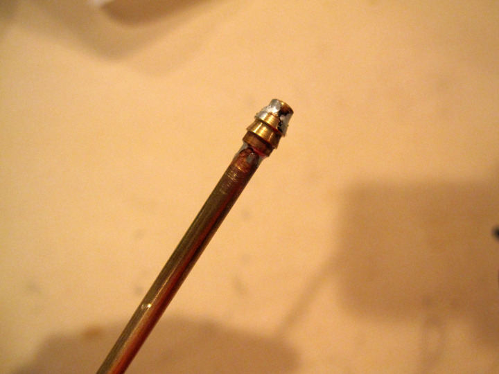
Carefully solder one Fuel Barb on each brass tube that will have a clunk. The vent line tube does not require a Fuel Bard. Make sure the barbs point in the right direction. The barbs should point down toward the short end of the tubing. This allows the barbs to hold the tubing when the tubing is pulled back.
Initial Fuel Tank Cap Assembly
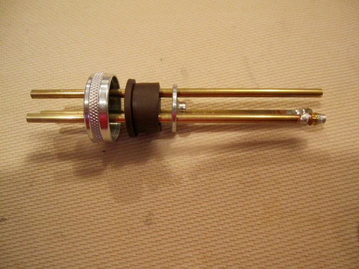
Assemble the Fuel Tank Cap - The order goes Aluminum Cap - Fuel Stopper - Fuel Tank Cap Back Plate. Line up the tube holes on each piece and slide the brass tubing through each hole. Make sure the Fuel Barbs will be on the side inside of the tank. (Note: Depending on the which Gas Fuel Stopper you use and how many clunks you will use, you may have open one of the holes on the stopper.)
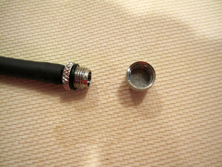
Filtered Clunk
The Clunk line consists of a Clunk and some fuel line that connects to the Fuel Barbs on the brass tubing. There are many different types of Clunks out there, I prefer the PSP Filtered Clunk, as it includes a micro-screen that allows good fuel flow, and keeps any gunk from getting to your engine. These Filtered Clunks are available here: Click Here.
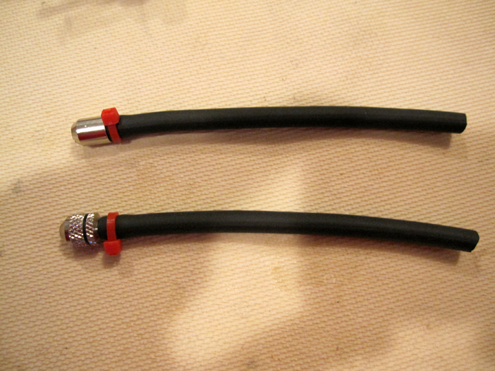
Clunk Line Setup - Part #1
You'll have to decide on the Gas Fuel Line you want to use inside of the fuel tank - see above for info on Gas Fuel Line. For this tutorial, I'm using my favourite "in-tank" fuel line - VITON.
Once you have decided on the "in-tank" Gas Fuel Line - you will need to measure and cut how much you will need so that the clunk will reach the back and bottom of the fuel tank. Once you have the fuel line cut, you will need to attach each clunk to the fuel line and secure the clunks with small wire ties (I use wire ties because they hold up to Gasoline and they do not cut into the fuel line like metal wire wrap).
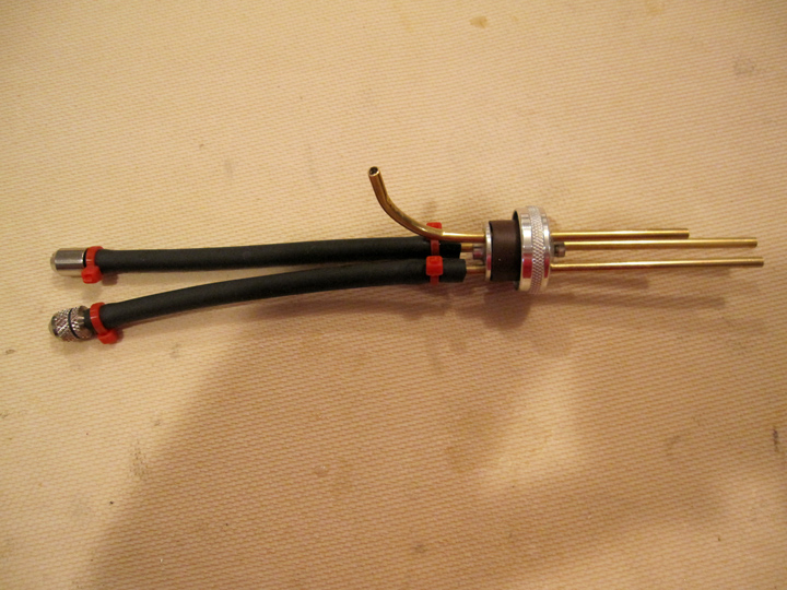
Clunk Line Setup - Part #2
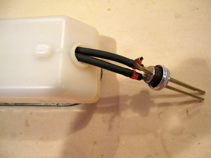
Attach the Clunk Lines to each brass tube (with Fuel Barbs) and secure the Clunk Lines with wire ties. At this time, you should also bend the in tank brass tubing as necessary. Make sure the vent line brass tubing points toward the top of the fuel tank, and that it is bent so that it is close to the top of the tank.
Fit Fuel Cap
Fit the Gas Fuel Cap to the Gas Fuel Tank by inserting the clunk lines and vent line into the tank. Make sure that everything fits correctly. Check each clunk to make sure it reaches the back and bottom of the fuel tank, and that the vent line is close to the top of the tank. The clunks should be able to move freely in the tank - they will move with the liquid as the planes moves through the air. It is sometimes helpful to hold the tank up to a bright light to see how the lines inside the tank are configured.
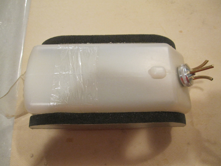
Completed Tank
With the Fuel Tank Cap fitted, tighten the Fuel Tank Cap screw. At this point, it is best to pressure test the Fuel Tank. To pressure test: Attach fuel lines to each brass tube. Block or pinch all of the Fuel Tubing lines, except for one. Submerge the entire Fuel Tank in water and blow into the one unplugged Fuel Line - You should feel the Fuel Tank Pressurize. If you see bubbles emerge anywhere on the fuel tank, around the Fuel Tank Cap or the submerged brass tubing, you have a leak that needs to be fixed. If you do not see any bubbles, you are good to go!
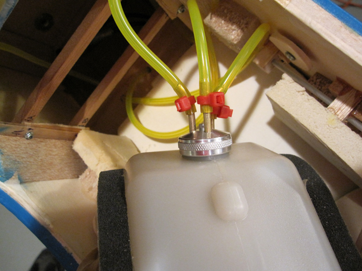
Finished!
You are now ready to attach external Fuel Lines to the Fuel Tank and then route them through your airframe. I usually use Tygon, because it holds up well (it will not be submerged in gasoline outside of the Fuel Tank) and it is transparent, so I can see the fuel flow through it. You may want to trim and/or bend the external brass tubing for your application, you can also use Fuel Line Barbs on the external brass tube connections, but with Tygon it is generally not necessary. I usually just use wire ties.
That's it - you're ready to go!
|